Ic Engines Pdf
EBook free PDF download on Internal Combustion Engine Fundamentals by John B.Heywood. Book download link provided by Engineering Study Material (ESM). The largest reciprocating IC are low speed CI engines of this type; they are used for marine propulsion (see marine diesel engine) or electric power generation and achieve the highest thermal efficiencies among internal combustion engines of any kind. 4.1 Spark Ignition Engines 231 where 'Y is the ratio of specific heats, cilcu' and M is the molecular weight of the gas; as is of the order of 500 to 1000 m s- for typical temperatures in internal combustion engines. For a cylinder 10 cm in diameter, the time required for a pressure disturbance.
Book Title : Internal Combustion Engine Fundamentals
Author(s) : John B.Heywood
Publisher : McGraw Hill
Pages : 481
PDF size : 42.2 MB
Book Description:
This text, by a leading authority in the field, presents a fundamental and factual development of the science and engineering underlying the design of combustion engines and turbines. An extensive illustration program supports the concepts and theories discussed.
Table of Contents:
Preface
Commonly Used Symbols, Subscripts, and Abbreviations
Chapter 1: Engine Types and Their Operation
Chapter 2: Engine Design and Operating Parameters
Chapter 3: Thermochemistry of Fuel-Air Mixtures
Chapter 4: Properties of Working Fluids
Chapter 5: Ideal Models of Engine Cycles
Chapter 6: Gas Exchange Processes
Chapter 7: SI Engine Fuel Metering and Manifold Phenomena
Chapter 8: Charge Motion within the Cylinder
Chapter 9: Combustion in Spark-Ignition Engines
Chapter 10: Combustion in Compression-Ignition Engines
Chapter 11: Pollutant Formation and Control
Chapter 12: Engine Heat Transfer
Chapter 13: Engine Friction and Lubrication
Chapter 14: Modeling Real Engine Flow and Combustion Processes
Chapter 15: Engine Operating Characteristics
Appendixes
Index
Download PDF
IC Engine
Published on Jan 10, 2016
Abstract
The Internal Combustion Engine is an engine in which the combustion of a fuel (generally, fossil fuel) occurs with an oxidizer (usually air) in a combustion chamber. In an internal combustion engine the expansion of the high temperature and pressure gases, which are produced by the combustion, directly applies force to a movable component of the engine, such as the pistons or turbine blades and by moving it over a distance, generate useful mechanical energy.
The term internal combustion engine usually refers to an engine in which combustion is intermittent, such as the more familiar four-stroke and two-stroke piston engines, along with variants, such as the Wankel rotary engine. A second class of internal combustion engines use continuous combustion: gas turbines, jet engines and most rocket engines.
Invention of the two-stroke cycle is attributed to Scottish engineer Dugald Clerk who in 1881 patented his design, his engine having a separate charging cylinder. The crankcase-scavenged engine, employing the area below the piston as a charging pump, is generally credited to Englishman Joseph Day (and Frederick Cock for the piston-controlled inlet port).
A two-stroke engine is an internal combustion engine that completes the thermodynamic cycle in two movements of the piston compared to twice that number for a four-stroke engine. This increased efficiency is accomplished by using the beginning of the compression stroke and the end of the combustion stroke to perform simultaneously the intake and exhaust (or scavenging) functions. In this way two-stroke engines often provide strikingly high specific power. Gasoline (spark ignition) versions are particularly useful in lightweight (portable) applications such as chainsaws and the concept is also used in diesel compression ignition engines in large and non-weight sensitive applications such as ships and locomotives.
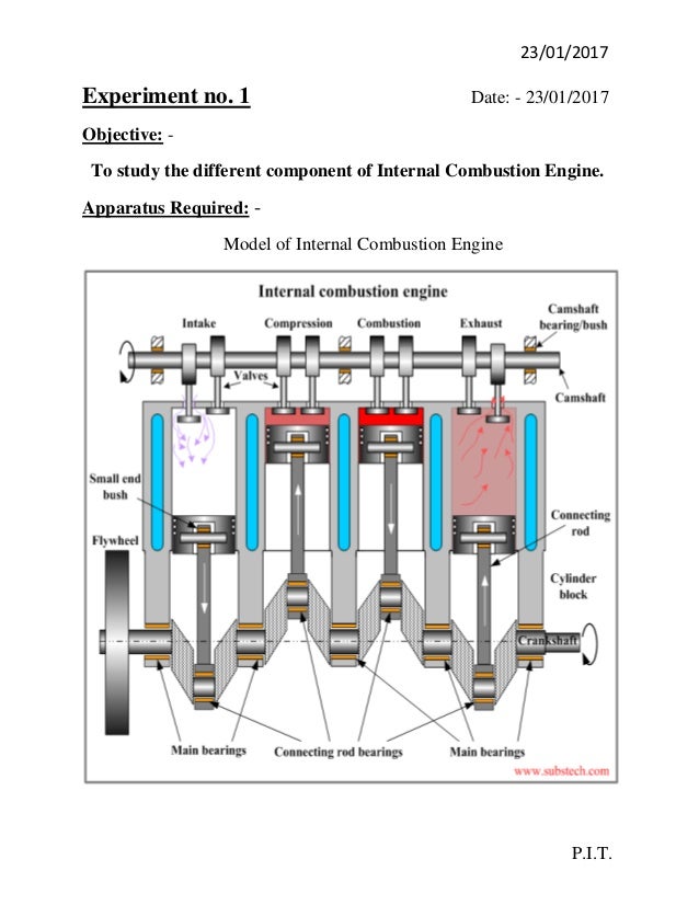
Today, internal combustion engines in cars, trucks, motorcycles, aircraft, construction machinery and many others, most commonly use a four-stroke cycle. The four strokes refer to intake, compression, combustion (power), and exhaust strokes that occur during two crankshaft rotations per working cycle of the gasoline engine and diesel engine. A less technical description of the four-stroke cycle is, 'Suction, Compression, Ignition, Exhaust' The cycle begins at top dead center (TDC), when the piston is farthest away from the axis of the crankshaft. A stroke refers to the full travel of the piston from Top Dead Center (TDC) to Bottom Dead Center (BDC).
Common Rail Direct Fuel Injection (CRDi) Engines :
Common rail direct fuel injection is a modern variant of direct fuel injection system for petrol and diesel engines. On diesel engines, it features a high-pressure (over 1,000 bar/15,000 psi) fuel rail feeding individual solenoid valves, as opposed to low-pressure fuel pump feeding unit injectors. Third-generation common rail diesels now feature piezoelectric injectors for increased precision, with fuel pressures up to 1,800 bar/26,000 psi.
The common rail system prototype was developed in the late 1960s by Robert Huber of Switzerland and the technology further developed by Dr. Marco Ganser at the Swiss Federal Institute of Technology in Zurich, later of Ganser-Hydromag AG (est.1995) in Oberägeri.
The first successful usage in production vehicle began in Japan by the mid-1990s. Dr. Shohei Itoh and Masahiko Miyaki of the Denso Corporation, a Japanese automotive parts manufacturer, developed the common rail fuel system for heavy duty vehicles and turned it into practical use on their ECD-U2 common-rail system mounted on the Hino Rising Ranger truck and sold for general use in 1995. Denso claims the first commercial high pressure common rail system in 1995.

Modern common rail systems, whilst working on the same principle, are governed by an engine control unit (ECU) which opens each injector electronically rather than mechanically. This was extensively prototyped in the 1990s with collaboration between Magneti Marelli, Centro Ricerche Fiat and Elasis. After research and development by the Fiat Group, the design was acquired by the German company Robert Bosch GmbH for completion of development and refinement for mass-production. In hindsight the sale appeared to be a tactical error for Fiat as the new technology proved to be highly profitable.

The company had little choice but to sell, however, as it was in a poor financial state at the time and lacked the resources to complete development on its own.[3] In 1997 they extended its use for passenger cars. The first passenger car that used the common rail system was the 1997 model Alfa Romeo 156 1.9 JTD,[4] and later on that same year Mercedes-Benz C 220 CDI.
Common rail engines have been used in marine and locomotive applications for some time. The Cooper-Bessemer GN-8 (circa 1942) is an example of a hydraulically operated common rail diesel engine, also known as a modified common rail.
Principle
Solenoid or piezoelectric valves make possible fine electronic control over the fuel injection time and quantity, and the higher pressure that the common rail technology makes available provides better fuel atomisation. In order to lower engine noise the engine's electronic control unit can inject a small amount of diesel just before the main injection event ('pilot' injection), thus reducing its explosiveness and vibration, as well as optimising injection timing and quantity for variations in fuel quality, cold starting, and so on. Some advanced common rail fuel systems perform as many as five injections per stroke.
Common rail engines require no heating up time [citation needed] and produce lower engine noise and emissions than older systems.
Diesel engines have historically used various forms of fuel injection. Two common types include the unit injection system and the distributor/inline pump systems (See diesel engine and unit injector for more information). While these older systems provided accurate fuel quantity and injection timing control they were limited by several factors:
* They were cam driven and injection pressure was proportional to engine speed. This typically meant that the highest injection pressure could only be achieved at the highest engine speed and the maximum achievable injection pressure decreased as engine speed decreased. This relationship is true with all pumps, even those used on common rail systems; with the unit or distributor systems, however, the injection pressure is tied to the instantaneous pressure of a single pumping event with no accumulator and thus the relationship is more prominent and troublesome.
Ic Engine Pdf Nptel
More Seminar Topics:
Ejection Seat,Electro-Hydraulic Brake (EHB) System,Electronic Fuel Injection,Flying Windmills,Four-Wheel Steering System,Freeze Drying,Frictionless Compressor,Full Authority Digital Engine Control,Geothermal Energy,Geothermal Energy,Homogeneous Charge Compression Ignition HCCI,Heat Pipe,High Speed Trains,Hot Runner Technology,Hybrid Car,Hybrid solar Desiccant Cooling System,Hydroforming Techniques,Hypercar,Hyperplane,IC EngineIc Engines Basics Pdf
